

How To Change A Hydraulic Clutch Lever
left right 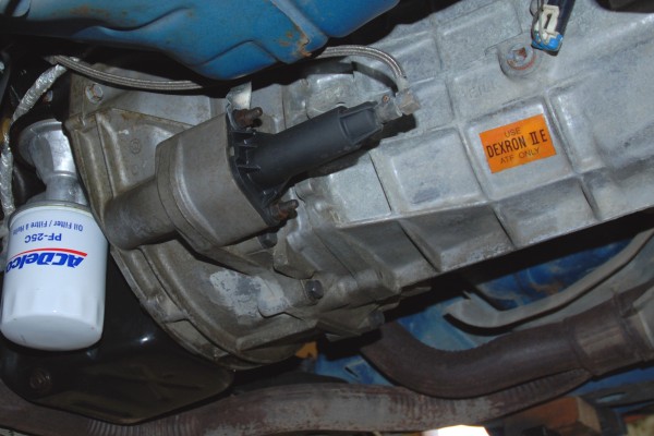


There are ii ways y'all can release a clutch on a car or truck—with mechanical linkage or via hydraulics. In this story, we'll explore the hydraulic clutch.
Slave Cylinders vs. Hydraulic Bearings
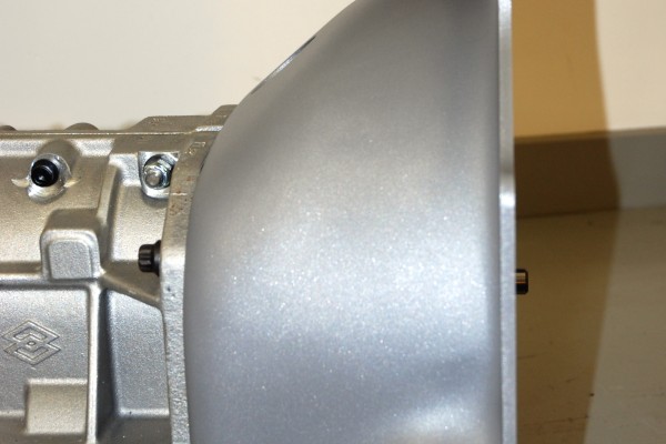
In that location are two bones types of hydraulic clutches: slave cylinder and release begetting. In a slave cylinder arrangement, a hydraulic cylinder is installed on the bellhousing and connected to a mechanical clutch fork. A clutch master cylinder feeds the slave cylinder. When you press on the clutch pedal, the pressure forces fluid from the chief cylinder to the slave; the slave cylinder moves the clutch fork, which in turn activates the clutch release bearing.
Detroit has used various configurations of this arrangement over the years. In some systems, the slave cylinder pulls the clutch fork; in others the slave cylinder pushes against the fork. The photo captions above will prove yous how a typical later model Chevy slave cylinder system is set.
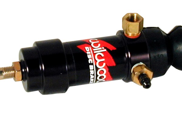
Several aftermarket manufacturers offer quality slave and principal cylinders. Wilwood'south "pull type" slave setup is a good example. The slave cylinder is manufactured from billet aluminum and has a stainless steel pushrod with a longer stroke (i.38 inches) than about cylinders. That guarantees full clutch release. Wilwood designed the slave cylinder for use with a 7/8-inch bore master cylinder. If you have packaging issues under the hood, Wilwood offers their Compact Serial slave cylinder. Information technology has an ultra-brusk 3.37-inch trunk but provides 1.12 inches of stroke.
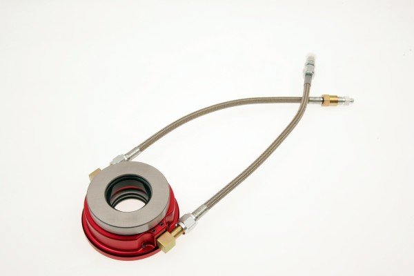
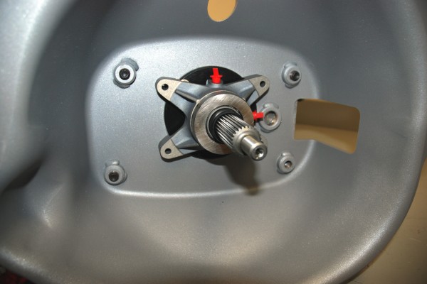
Slave cylinder systems are simple, but the hydraulic release begetting is simpler still. There is no slave cylinder or clutch fork. Instead, the clutch master cylinder applies hydraulic pressure straight to the bearing that engages the pressure plate fingers. A hose running directly from the clutch main cylinder to the primary cylinder replaces near all of the mechanical parts.
In that location are several different designs of hydraulic release bearings available. I is the floating bearing offered past McLeod and others. This type of bearing works much like a regular release bearing, except information technology is engaged via hydraulics instead of mechanics. The other blazon is the stock-still release bearing offered by Tilton. The bearing is either physically bolted to the inside of the bellhousing (you take to use a defended Tilton bellhousing for this) or it can be bolted to the manual. When mounted straight to the gearbox, the stock input shaft retainer must be swapped for one of Tilton's retainers. Tilton offers begetting/servant packages for everything from vintage Muncies to modern Tremecs. They also offer a generic input shaft servant that you can machine for not-so-mutual applications.
High performance hydraulic release bearings are "constant contact" types that provide quick clutch response. You will need to gear up a small operating clearance betwixt the bearing and the pressure plate. Once you have the bearing properly adjusted for clearance, it will self-adjust for habiliment. That'south because there is no render spring required to pull the begetting'south piston back to the bottomed position. The piston within the associates functions much similar the piston in a restriction caliper. Clutch pedal feel remains the same as the bearing wears, too.
Installation of a hydraulic release begetting is straightforward: Virtually bearings have a straight -3 AN matrimony fitting installed for the master cylinder plumbing as well as a second -3 AN fitting for a bleeder hose. Tilton recommends a 7/eight-inch bore chief cylinder for a street clutch, while McLeod usually recommends a 3/4-inch bore principal cylinder.
Determining Pedal Ratio
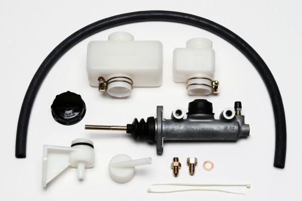
The key to a hydraulic clutch setup is getting the pedal ratio correct. In fact, it'southward critical, and an inch or two can make all the difference in how the clutch performs. Simply like a brake pedal, the clutch pedal acts as a lever to increment the force applied by the driver to the master cylinder. That forcefulness tells the main cylinder to ship fluid to the release bearing or clutch slave.
If you lot examine a clutch pedal, you'll see the pin point (where the pedal moves) and the mounting point/pigsty for the main cylinder pushrod are quite often different. By varying the length of the pedal and/or the altitude between the pushrod mount and the pedal pin, y'all can change how much forcefulness (via your left leg) is required to energize the master cylinder. This is the mechanical reward, or pedal ratio. What you demand to do is to figure out a ratio that provides enough force to energize the primary cylinder without requiring too much endeavour on your leg's part.
Let's start at the beginning. The typical adult male leg can exert roughly 300 pounds of strength. If yous've ever tried to single-leg press 300 pounds at a gym, you know that's a bunch. When you're figuring out the right pedal ratio for the clutch, shoot for a force number that is 1/3 or less than that 300 pound effigy. That will make working the clutch much more than comfortable.
Side by side, yous have to translate that 100 or so pounds of leg strength into approximately 600 psi. You can do this by changing the overall length of the pedal, but information technology's usually easier (and far more practical) to shorten the distance betwixt the pin point and the chief cylinder pushrod mount location by drilling a pigsty for a new pushrod location.
If you go overboard in the pedal ratio department, the clutch can get over-sensitive or touchy. Then how do you become it right? Start, you need some measurements:
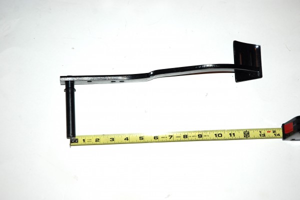
- Height of the pedal from the very bottom through the centerline of the pivot point
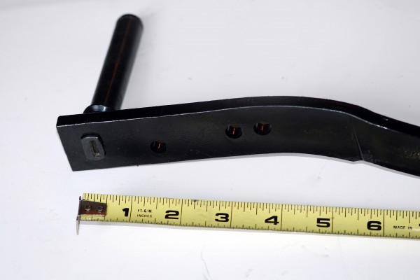
- Center-to-eye measurement through the pivot betoken and the clutch pushrod pigsty in the pedal lever
Using an aftermarket reproduction clutch pedal as the case, dimension #1 is 13.25 inches. There are two different stock pushrod holes available (measurement #2): three inches and 3.625 inches. To decide pedal ratio, split effigy #1 by #2. Here's how the ratios look for our example:
13.25 / iii = four.41 ratio
13.25 / 3.625 = 3.63 ratio
The recommended pedal ratio with either a 7/8- or iii/4-inch diameter clutch master cylinder is around 6:ane, and so nosotros would need to drill a new pushrod hole approximately 2.2 inches from the pivot indicate to get the optimum pedal ratio (13.25 / two.2 = 6.072).
Take a look at the photos and captions in a higher place to come across how simple a hydraulic clutch system actually is. In a few weeks, we'll look at some mechanical linkage options.
Source: https://www.onallcylinders.com/2013/07/05/please-release-me-how-to-set-up-a-hydraulic-clutch/
Posted by: chavezhond1975.blogspot.com
0 Response to "How To Change A Hydraulic Clutch Lever"
Post a Comment